If you’re asking what is a flange, the most practical engineering answer is this: a flange is a shaped rim, collar, or plate — most often with bolt holes — used to connect components so fluids, pressure, and loads can be handled safely and serviceably. In piping and industrial equipment, flanges make it possible to assemble, dismantle, inspect, and maintain systems without cutting and rewelding every time. That combination of strength, sealing, and removability is exactly why flanges show up everywhere from water plants to refineries.
What Is a Flange in Engineering?
In engineering, a flange is an interface designed to join two parts so they behave as one continuous system. Depending on the application, it can also reinforce a structure, provide a mounting edge, or create a reliable sealing surface. The most common industrial meaning is the bolted joint you see on pipes, valves, pumps, heat exchangers, and pressure vessels.
A flange connection typically works because two machined faces meet, a gasket is compressed between them, and the bolts supply the clamping force needed to maintain sealing under internal pressure and operating loads. That last part matters more than many people expect: a flange isn’t just “metal on metal.” It is a joint system that includes the flange faces, the gasket, the bolts or studs, the tightening method, and the operating environment.
Why Flanges Are So Common in Industry
Flanges are popular because they solve a real maintenance and safety problem. Welded piping is strong and compact, but it’s not inherently serviceable. When a plant needs to replace a valve, install an orifice plate, remove a strainer basket, or inspect a nozzle, a flanged connection allows that work to happen without major rework.
Flanges also enable interchangeability when everyone follows recognized standards. That’s why engineers don’t just specify “a flange.” They specify a standard, size, pressure rating or class, facing type, and material. When those match, parts from different manufacturers can bolt together predictably.
This is where standards like ASME B16.5 become central to daily engineering. ASME’s own description of B16.5 explains that it covers pressure-temperature ratings, materials, dimensions, tolerances, marking, testing, and methods of designating openings for pipe flanges and flanged fittings.
The Core Function of a Flange
A flange usually exists to do three jobs at the same time: connect, seal, and manage loads.
Connection is the obvious one. Flanges create a removable joint that can be repeatedly assembled and disassembled. In real plants, that repeatability is a major lifecycle advantage.
Sealing is the job that gets the most attention, because leaks are expensive and sometimes dangerous. Flange faces are engineered so a gasket can be compressed in a controlled way, which helps the joint resist leakage across pressure and temperature changes.
Load management is the job that gets underestimated. Flanges don’t only “hold pressure.” They also see bending loads from piping weight, vibration from rotating equipment, thermal expansion forces, and misalignment stresses. When flange selection is wrong, the symptom is often repeated gasket failures or chronic weeping at joints even after “tightening it more.”
Standards That Define Flanges and Why They Matter
Flanges are highly standardized because standardization reduces risk and improves fit-up.
ASME B16.5 is one of the best-known standards for many common pipe flange applications. Its scope statement is widely referenced because it clarifies exactly what B16.5 covers and why it’s trusted for piping compatibility.
ISO standards are also widely used, especially in international supply chains. ISO 7005-1:2011 describes itself as a base specification for steel pipe flanges suitable for general purpose and industrial applications, including chemical process industries, electric power generation, and petroleum and natural gas industries.
There’s also a standard that speaks directly to how flanges are assembled in the field. ASME PCC-1 focuses on pressure-boundary bolted flange joint assembly guidance and helps organizations develop consistent joint assembly practices.
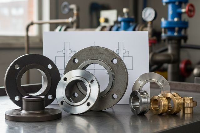
Common Types of Flanges and Where Engineers Use Them
Different flange types exist because different services demand different combinations of strength, fatigue performance, cost, and ease of installation.
A weld neck flange is known for its tapered hub and butt-weld connection to the pipe. That geometry spreads stresses more smoothly and is often favored for higher pressure, higher temperature, and cyclic service where vibration and thermal cycling can punish weaker joints.
A slip-on flange is generally easier to fit because it slips over the pipe and is welded. In many moderate services it performs well and is cost-effective, but it is often less preferred in severe cyclic or high-integrity situations compared with a weld neck.
A socket weld flange is common in smaller bore piping because it is compact and straightforward to install. It can be a solid choice when specified and fabricated correctly, particularly in small sizes.
A threaded flange can be used where welding is undesirable or restricted. It can simplify installation in certain environments, but engineers are typically careful about using threaded joints in services with heavy cycling, vibration, or high temperature.
A lap joint flange pairs with a stub end, and the flange ring can rotate. That rotation can make bolt alignment easier during assembly and can reduce installation time in systems that need frequent opening. In some corrosion-resistant systems, it also allows the flange ring to be a different material than the wetted stub end, which can reduce cost.
Flange Faces and Sealing Surfaces
Flange facing describes the sealing surface geometry, and it influences gasket selection and leak performance.
Raised face configurations are common in process piping because the raised portion concentrates gasket stress and can help create a reliable seal when assembled properly.
Flat face configurations distribute load across the full face and are often used in certain equipment or materials where design practice calls for it.
Ring-type joint configurations use a machined groove and a metal ring gasket. They are common in higher-pressure or higher-integrity applications where metal-to-metal sealing behavior can be advantageous when designed and assembled correctly.
Where Flanges Are Used in the Real World
Oil and gas facilities use flanges in pipelines, valve stations, compressor skids, and many equipment tie-ins because flanged joints are serviceable and compatible with standardized components. ISO 7005-1 explicitly calls out petroleum and natural gas among the industries within its broad application scope.
Chemical and petrochemical plants use flanges heavily around pumps, control valves, instrumentation points, and heat exchangers, especially where periodic maintenance is expected and where piping modifications happen over time.
Power generation uses flanges in auxiliary systems and certain steam and water services, particularly around equipment interfaces where planned maintenance is routine.
Water and wastewater systems commonly use flanged joints for larger diameters and for equipment connections because being able to isolate and open lines for inspection is practical and cost-saving.
HVAC and building services use flanges at pumps, chillers, and large valves for similar maintenance reasons, especially in commercial and industrial buildings.
Why Flanges Leak and Why Tightening “Harder” Isn’t a Strategy
Many people first learn about flanges when one leaks. What matters is that flange leakage is rarely caused by a single factor. It’s usually the result of how several variables stack up: gasket selection, surface condition, alignment, bolt condition, lubrication, tightening method, and operating cycles.
Bolt preload is the hidden variable. If preload is too low or uneven, the gasket doesn’t get enough compressive stress and the joint can leak under pressure or during temperature changes. If preload is too high, you can crush the gasket, damage the flange face, or yield bolts, all of which can create future leakage.
A helpful way to understand why “torque-to-tighten” can be inconsistent is to look at how uncertain preload can be when torque is applied. A NASA technical memorandum on preloaded joint analysis notes that it is generally safe to assume preload uncertainty for a hand-operated torque wrench used on a lubricated fastener is about plus or minus twenty-five percent, and that instrumented approaches can reduce that uncertainty significantly.
This is one reason guidance like ASME PCC-1 is so valuable in industry. It focuses on bolted flange joint assembly practices that organizations can adapt into procedures for more consistent outcomes.
A Practical Scenario That Shows How Flange Choice Changes
Consider a cooling water line at ambient temperature and moderate pressure. In many plants, cost and ease of installation matter, and the consequence of a small leak may be manageable. A more economical flange style might be acceptable, provided it meets the specified pressure rating and the assembly practice is sound.
Now consider a hot hydrocarbon line that experiences frequent temperature cycling and sits near vibrating equipment. In that case, engineers usually prioritize higher integrity, fatigue performance, and sealing robustness, because leaks can have safety, environmental, and downtime consequences. This is where flange type selection, facing choice, gasket compatibility, and tightening method tend to become more conservative.
The key insight is that “what flange is best” is not universal. It depends on the service severity, the duty cycle, the maintenance philosophy, and the acceptable risk.
Actionable Tips Engineers Use to Improve Flange Reliability
When you want fewer leaks and fewer repeat maintenance events, the biggest gains usually come from consistency and control.
Start by matching the flange specification to recognized standards for dimensional compatibility and rating logic. ASME B16.5 is widely used in many piping systems for exactly that reason.
Next, treat assembly as part of the design. Procedures aligned with recognized guidance, such as ASME PCC-1, can help organizations reduce “installer variability” and build repeatable quality into bolted joints.
Finally, pay attention to the things that quietly change preload outcomes, like lubrication consistency, bolt condition, and alignment. The goal is not simply “more torque.” The goal is achieving the right and evenly distributed gasket stress.
Market Context: Why Flanges Get So Much Industry Focus
Flanges are not niche parts. They are used at massive scale across infrastructure and industrial projects, which is why reliability improvements can create outsized savings.
One example market estimate from Global Market Insights reports the global flanges market at about USD 5.7 billion in 2024, with projected growth over the next decade.
Even if you never use market numbers in engineering calculations, the implication is real: widespread use means flange failures, leaks, and rework can add up quickly across a facility or across a fleet of assets.
FAQ: Quick Answers for Featured Snippets
What is a flange used for?
A flange is used to connect components, usually with bolts and a gasket, so the joint can be sealed under pressure and later opened for maintenance.
What is the difference between a flange and a fitting?
A flange is primarily a connection interface, while a fitting is typically used to change direction, size, or routing. Many fittings can be flanged, meaning they include flange ends designed for bolting. ASME B16.5 explicitly addresses pipe flanges and flanged fittings in its scope description.
Why do flange joints leak?
Flange joints often leak because gasket stress is insufficient or uneven, the gasket is incompatible with the service, the faces are damaged, the joint is misaligned, or bolt preload changes over time due to cycling. Assembly guidance like ASME PCC-1 exists because these details strongly influence joint performance.
Are all flanges interchangeable?
Flanges are only interchangeable when the standard, size, rating or class, facing, and bolt pattern match. If any of these differ, even slightly, you may get assembly issues or poor sealing.
How do I choose the right flange?
Choose based on the piping standard used, the pressure-temperature requirements, material compatibility, facing and gasket strategy, service severity, and maintenance needs. ISO 7005-1 and ASME B16.5 are examples of standards that define baseline requirements and compatibility rules.
Conclusion: What Is a Flange and Why It Matters
To wrap it up, what is a flange in engineering? It’s a designed interface that connects components while enabling sealing and service access, especially in piping and pressure equipment. Flanges are trusted because they’re standardized, widely supported, and maintainable, but their reliability depends on treating them as a complete joint system. When you align your specifications with recognized standards such as ASME B16.5 and ISO 7005-1, and you apply disciplined assembly practices such as those addressed by ASME PCC-1, you reduce leakage risk and improve uptime.